About Me

My photo
Santa Clarita, Ca, United States
I work as a Technology Manager in the Entertainment Industry. My first film was Disney's Dinosaur and have been credited on several films since. I love working on old electronics, especially old radios. I am also passionate about technology and education. I have 4 kids and you can read about us on our family blog.

Sunday, November 13, 2016

Decca 700 Radio Turntable


This one arrived in need of a lot of work.  The turntable didn't turn, the radio was weak, and there was a typical 60hz hum in the speakers.  First to tackle was the electrical repair.  I opened up the case to take a look.  Inside was a small metal chassis with 6 tubes. 


The back of the radio had a simple drawing of the tubes included.


 I cleaned it up in Gimp


Although the tubes were in series, this was not a typical "All American Five" setup.  There was no rectifier tube and there were two 35C5 audio output tubes. Instead of a rectifier tube, there was a Selenium Rectifier.  It can be seen in this picture as the stacked blue wafers in the upper left.  I typically see these in radios from the late 50's or early 60's. 


In order to solder in the new capacitors, I had to get to the base of the original.  It was underneath the Selenium Rectifier so I had to move it aside. 


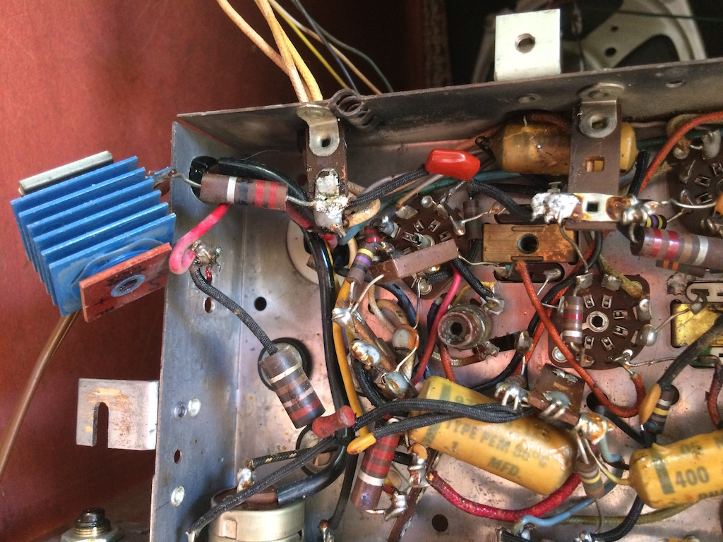
The original electrolytic capacitor was three sections of 150V and 40mfd each.  I soldered in three 160V 47mfd capacitors.  I tested each before installing and they all measured at 39.6mfd.  It's interesting that the tolerances are off by that much, but fine for this.  You can see the new capacitors in the lower middle of the chassis here. 


While I had the radio open, I went ahead and tested all the tubes.  I very rarely find bad tubes.   Capacitors fail all the time, but tubes can last for decades.  Turns out though, this radio had one weak (35C5 Audio Output) and one bad tube (12BE6 Pentagrid Converter) so I replaced them both.  Perhaps this is why the reception was so poor.   Fortunately, I keep all the tubes for this radio in stock. 


With  electrical repairs done, I tested the radio and it sounded great. It was time to tackle mechanical repairs.  First was the dial.  The cord was slipping on the tuning shaft so I was not able to tune the radio.  You can see here how polished it was.

I thought about putting on a new cord, but I hate stringing radio dials. I tried rouging up the shaft, but no success. I made sure all the pulleys were working fine,. still no success.  I then got creative.  I coated the shaft with a rubber coating.   Yeah, this feels like cheating, but it totally worked.


While I had the radio open I added a second cable for an MP3 player.  I ran it up near the turntable so I can play audio from a headphone jack into the audio input.  I tested it out with my phone and it sounded great.


 Next was the turntable.  The idler wheel was not making consistent contact with the turntable so it was slipping.  These are impossible to buy new now days.  You can get used ones on Ebay for around $15-$20, but they are no better than the broken originals. Since I was going to be getting creative I decided to buy a used one anyway.  Once it arrived, I coated it in "Parts Dip" that is used for handles on tools.  This gave it extra thickness and much "stickier" rubber. You can see it on the left with the "Re Tread".


 I then installed on the turntable.  The turntable was running, but there was still a problem.  The wheel didn't align properly with the motor.  This was because the grommets that hold the motor in place had grown old and flattened.  The motor was lower than it was supposed to be.

 I didn't have any suitable grommets around, nor am I sure it's possible to purchase any so I had to improvise and use faucet washers.  This actually worked fine and the turntable was back in business!

I put everything back together and tested it out and the radio and turntable are working great.


 Everything was working so I brought it to work.  Here's how it looks in my office at work.


Monday, September 5, 2016

Motorola 53C Clock Radio

This radio came from my wife's grandmother.  It was her bedside radio for many years .  It was passed down to my wife and she had it on her dresser. She had not yet tried to use it as a clock, or a radio.   I offered to check it out and make sure it was working before she put power to it.


The radio is another "All American Five" configuration with five tubes.  This one uses the 12AT6 instead of the 12AV6 for the detector/first audio amplifier.  Tube compliment is 12AT6, 12BA6, 12BE6, 35W4, and 50C5.

Tube compliments in the All American Five can very.  For anyone interested, here are some of the typical tube numbers .

Tube Type
Pentagrid Converter
IF
Detector
AF
Rectifier
5 Pin Early Style 6A7 6D6 or 78 75 43 25Z5
Octals with Anode Cap 12A8 12K7 12Q7 50L6 35Z4
Octals w/o Anode Cap 12SA7 12SK7 12SQ7 50L6 35Z5
Miniature "Peanut" Tubes 12BE6 12BA6 12A6 / 12AT6 50B5 /
50C5
35W4

Back to the radio..

On initial power up,  there  was the typical 60hz hum you hear when the filter capacitors have failed.  I removed the original and replaced it with new Electrolytics.


I've started getting in the habit of testing my capacitors after I pull them out.  Here's how this old paper electrolytic faired. 

Section Labeled Capacitance Actual Measured Replaced With New
1 150V 50 uf (MFD) .078 uf (MFD) 160V 68 uf (MFD)
2 150V 50 uf (MFD) .070 uf (MFD) 160V 68uf (MFD)


New capacitors in place. 


Here it is with the old one in place for size comparison.


Second problem appeared to be a broken screw mount for the chassis.  The broken off piece was rattling within the case.  This was repaired with Epoxy.


Third problem was a groaning/whirring noise from the clock movement.  This clock has a classic "Telechron" movement.  It's a sealed inductive gear system that uses the 60hz power to run a gear reduction motor.  Removing the clock mechanism would involve removing the front.  This meant I had to pry off the plastic cover to the radio dial. This is where you have to pry VERY CAREFULLY.  


Here's the clock internals.


The Telechron movement was an H3 Model.  Turns out, you can purchase these rebuilt.  I found a very nice web site with rebuilt version of all the Telechron movements.  What a great site!!  Since this is a learning project (as are all my projects), I decided to try to lubricate the movement myself.  I used 3-in-1 oil (my go-to oil for these kinds of things).  The movement is sealed so there's no way to oil it directly. I put the oil around the gear and tried to work it in by moving the gear up and down as much as it would move.  A  small amount did appear to leak past the gear.


I then re-installed the motor.  It was reasonably quiet.  If the problem comes back, I'll probably revisit the Telechron rebuild site and pick up a fresh H3 movement, but this one is working fine for now.  I'm not sure how much my wife will be using the clock so I'll let her decide if she wants to keep it running or not.

GE Model 429 "Dial Beam" AM Radio

My dad had this radio in his living room in pieces.  Someone had tried to fix it and he picked it up at a garage sale for a few dollars.  The speaker was missing, the knobs were missing,  pilot light was burnt out, and it was covered in dust, dirt and grime.  Though, it's a nice looking radio and it caught my eye so I decided to fix it up.  Here it is the way I found it (with some knobs added for testing).


Nifty "Dial Beam" logo.


The radio is a typical "All American Five" tube radio with a 12AV6, 12BA6, 12BE6, 35W4, and 50C5.  This tube lineup was used in millions of radios.  If you are interested, there's a great Wikipedia article on the All American Five design. 

I hooked up my test speaker and powered up the radio. It had the typical 60hz hum that you get when the filter capacitors have failed so I replaced those first.  Here you can see the new ones soldered in.  I left the old red paper capacitor in place for comparison.  The new ones are the black ones to the left.


For those not familiar with this problem, it's pretty common.  Paper Electrolytic Capacitors tend to fail on old radios.  They are used in the power supply along with a rectifier tube (35W4 on this radio)  to convert your AC line current to DC.  When they fail, all you will hear on the old radio is a loud hum.  Changing the volume or station won't change the hum.  The only thing to do is to replace the old capacitors with new ones. It's a common problem so I keep several on hand.

I didn't have a speaker that fit properly so I ordered a few on line.  None seemed to fit just right.


However, turns out, my test speaker was exactly the right size, but had a lot of tears in the cone.  I awkwardly patched them with LocTite Go2 glue which is a really great all purpose glue.  It is strong, but somewhat flexible and glues most anything.  It didn't look pretty, but at least the speaker wan't full of holes any longer.


I still had weak and garbled audio at the speaker so I started to suspect the grid coupling capacitor that sits between the first audio stage (12AV6) and the control grid of the final audio stage (50C5).  It's what connects the audio signal between the tubes.  If it was off value, or leaking, it could be contributing to audio problems.  Unfortunately, this one was not going to be super simple to replace.  It was a multi-segment capacitor and no markings on the value.  The leads were mixed in with other wires and multiple components were soldered to each post.  Fun.


Since I didn't know the values of the K71J670 Multi Segment Capacitor, I was going to need to find a schematic of the same, or a similar radio.  I did some searching.  There was a schematic on RadioMuseum.org site, but I wasn't sure if it had the capacitor.


After a bit of searching, I struck gold on the Nostalgia Air Web site!  They had a schematic for a  GE 412,  that was very close.  The schematic showed the different sections of the capacitor and their values.


I used this as a guide to replace all the different sections of the old capacitor with brand new capacitors.  After replacing them all, the radio worked perfectly!!

However, I had to know...  Now that I had the capacitor out, I decided to test each of the sections to see what state they were actually in.   I  tested each section with my meter.  Here's the listed, and actual values as tested.


Section Schematic Listed Value Actual Value
1 C11 .002 uf .0022 uf
2 C10 400 pf 360 pf
3 C12 220 pf 210 pf
4 C12 .005 uf .005 uf

Wow!  Actually tested pretty good!!  At least, the capacitance values are correct. (My tester does not test leakage).   Maybe the capacitor was fine.  (Hmmm... did I hook up both wires of the antenna properly when I tested it?)  Oh, well, it's got new capacitors now.

I gave the case a good polish, replaced the burnt-out dial lamp, replaced the missing case screws, and cleaned up the dial.  The plastic face had a lot of dirt behind the plastic and I cleaned it.  This removed the paint from the numbers so I had to repaint them with fresh paint.


I put it all back together with new knobs and brought it in to work where it sits now.