About Me

My photo
Santa Clarita, Ca, United States
I work as a Technology Manager in the Entertainment Industry. My first film was Disney's Dinosaur and have been credited on several films since. I love working on old electronics, especially old radios. I am also passionate about technology and education. I have 4 kids and you can read about us on our family blog.

Wednesday, April 17, 2019

Learning Wet Plate Photography - Tintypes

Last year, we built a Telegraph for SCVi's Living History day.  This was a project with my daughter Emily and she did an amazing job learning morse code and working with her fellow 8th graders demonstrating 19th century communications.  For this year, it's Brandon's turn in 8th grade and he decided to take on an even more ambitious project - Wet Plate Photography!

Wet Plate Photography is one of the earliest photographic processes used from the 1850's to the 1880's. It involves making your film, chemicals, and sometimes even your camera from scratch.

Planning

This project required a lot of specialized supplies and pretty high learning curve.  I picked up Quinn Jacobson's book : Chemical Pictures The Wet Plate Collodion Book: Making Ambrotypes, Tintypes & Alumitypes to get started.  It was a great resource!

Obtaining Supplies

Chemicals

For the first pass, we sourced chemicals from multiple locations. Since we were doing this with an 8th grade class, we had to avoid the traditional Cyanide and Cadmium based chemicals.  This meant using Sodium Thiosulfate for the Fixer and using a non-cadmium collodion.

Here is a comprehensive list of everything we had to purchase. Although these are just starter quantities, it gives an idea of what you'll need to purchase to make your first few tintypes.   I have to give a call out to Bostick and Sullivan.  What a great resource! 


StepItems PurchasedCost
Step 1 : Pouring The PlateBostick & Sullivan Cadmium Free Collodion86.89
Modern Collodion Tintype Plates14.99
Ethyl Ether (For restoring collodion)38.65
Step 2: Sensitizing The PlateUPI Metals Silver Nitrate 100g85.61
Distilled Water From Grocery Store1
Step 3: Development95% Ethanol Alchohol35.35
Ferrous Sulfate 500g12.62
Glacial Acetic Acid 1000ml18.79
Distilled Water From Grocery Store
Step 4: FixingSodium Thiosulfate 500g7.04
Step 5: VarnishSandarac Varnish 250ml28.35
Total Cost329.29

If you prefer Amazon, some of these supplies are available there as well for similar prices:


Camera

For the camera, I decided to use our Graflex 4x5 sheet film camera with a Fim Pack adapter.  I had a few of them so it was an easy place to start.


The film pack adapter is not a perfect fit, but was fine for getting started.  We used Balsa Wood to add a little meat to the sides to make the fit a bit tighter.


Preparing The Chemicals

We decided to use 19th century Apothecary bottles to give an authentic appearance to our supplies.   Since we have a darkroom setup at the house, we used regular 5x7 photo trays for the chemicals. 


We used the recipes from Quinn's book to mix chemicals in the right quantities and proportions. 

Our First Tintype

Pouring The Plate

This is the first step of creating a tintype is to pour the collodion on to the plate.  This is arguably the most important, and also the most challenging part of the process.  Although I read instructions on this multiple times, it helped much more to have an example.  Fortunately, Quinn Jacobs has a nice  YouTube video showing how to do this.


Silver Bath

Second step is to dip the plate in Silver Nitrate bath for 3 minutes.  The silver nitrate reacts with the salts in the collodion to make light sensitive silver bromide.  Since the plate becomes light sensitive in this step, it has to be done in the darkroom.

Exposure

The light sensitive plate is loaded into the film holder.  We then have a few minutes to get it to the camera and expose the photo.  Since the film holder is light tight, it can leave the darkroom with the tintype inside of it.

Development

The film holder is brought back to the darkroom and developed in the developer for about half a minute.

Fixer

The tintype is moved to the fixer and this clears the plate so you can see it.  Once fixing is done, the plate is no longer light sensitive.

Results

Our first results fell pretty short of satisfactory.  Instead of the images we intended to photograph, we came out with muddy, cloudy images.  Although it was good to at least see were were getting some imagery, we weren't getting anything close to what we expected.


We theorized that we were both over-developing, and under-exposing.  We decided to do a simple print with just a simple object. 


This worked!  Although there were some pretty severe shortcomings in my ability to pour the plate. You can see that we have some density variation in the negative.  Maybe the way we are pouring it?  Also, there's some color in the dark part of the image.  Still more to learn, but we had basic proof of concept.  For the next phase, we set the camera up outside.  


We did exposures at F4 for 10, 5, 4, and 3 seconds.   These were not so lovely. However, we did have some things in there that looked like branches and vines.  I think we heavily overexposed. 


Looking closely in the sun, you can see some grape leaves and vines.  


Progress!!  Though we still have quite a way to go. We iterated on our process quite a bit, practicing our pouring, trying different exposures, being careful about development time, and finally started to get some decent results.  Here is the grape vine with a 2 second exposure at F4 with about 30 seconds in the developer.


With more practice, we were able to try photos of people.  Here's one of Brandon.  It was SO exciting to finally have something that looked like a photograph!


We took a couple more.  Here's Brandon and I after the plates dried.


We still have a few things to figure out...
  • Why do we have a gray haze on the plates coming out of the fixer? It washes off, but requires a wiping off with a thumb.  Is that normal? 
  • How long should we rinse? Should we use Hypo Clearing Agent? 
  • There's black specs in the photo.  Are those an impurity somewhere?  How do we get rid of them? 
We'll keep practicing and trying things.  Hope to have better images soon.  There's also a few classes I might consider taking to get some pro tips such as this one at Los Angeles Center of Photography.

Continue Reading : Up Next -> Attempting Wet Plate In The Field. 

Sunday, January 6, 2019

Matt's Vegetarian Black Bean Chili

I've made this several times for guests and parties at work.  I've been asked about the recipe.
  • 2 Medium Onions
  • 2 Tbsp Minced Garlic
  • 1 Can (7oz) chipotle peppers in adobo sauce
  • 2 tsp Oregano
  • 4 tsp salt
  • 1 oz Achiote paste
  • 2 Tbsp Cumin
  • 4 tsp Chili Powder
  • 8 cans black beans

Step 1: 

Mince the onions in a food processor.  Add the garlic and cook them down together with olive oil till the onion starts to turn translucent.


Step 2: 

Mince the chipotle peppers and other spices (Oregano, Chili Powder, Cumin, Achiote Paste) in a food processor. Add them with the salt to the grilled onion mixture. You will make a red colored paste which is the flavoring sauce for the beans.

Step 3: 

Add between 6-8 cans of black beans (depending on how spicy you want your chili) to a crock pot. Pour in the spice sauce made in steps 1 and 2.  Simmer in the crock pot for a couple hours till the mixture blends well.  If you like your chili to be more tangy, you can add up to 1/4 cup of ketchup to the mix.  This gives it more BBQ sauce flavor and reduces the hotness of the peppers a bit.


Serve with sour cream or cheese on top. 

Saturday, December 8, 2018

Precision Apparatus E-200C Signal Generator

I needed a signal generator for my repair bench and was considering purchasing one. There are many good options under $200 that can be considered.  However, my dad had several old ones in his collection  that were in unknown condition.  I chose this one as a project.


Overall, it's a pretty nice unit with a vernier dial and large display.  It also has 400Hz audio output for testing audio circuits.  It clearly was going to require some physical cleaning as well as some electrical repair.


The inside is well organized and easy to service.


I was able to find the manual on the Bama site : https://bama.edebris.com/manuals/paco/e200c/  It wasn't an exact match, but seemed reasonably close.

There did not appear to be consistent RF output.  I suspected the electrolytic filter capacitor and decided to swap it out. It was an interesting multi-section capacitor with the elements in series.


I created a similar setup with modern capacitors.  I used shrink tube to emulate the original color configuration. 


I could have left it like this, but I thought it would be nice to keep the original appearance.


I always enjoy the challenge of trying to maintain original appearances on equipment so I hollowed out the original cardboard shell and placed the new capacitors inside. 


 I tested all the tubes and they all tested new.  Some of the dials were flaky so I cleaned them all with electrical cleaner and that brought them all back to life. I then tested it out.  My desktop multimeter has a frequency counter so I hooked it up to the Signal Generator.  The 130Khz setting (inner circle on dial) shows 130Khz on the meter. Looks good!


 Should be a useful tool for future projects. The next step was to work out the leads. This device has an old style Amphenol 75 series microphone connector.

I'd have to make a choice, do I swap out the connectors for something modern (i.e. BNC connectors), or try to find the old style plug?  I decided to quest for the original style plug.  Found one at Surplus Sales.  It's an Amphenol 75-MC1F.  There were also some good options on Ebay.  I was able to build a cable.


I then ran it through its paces with the cable in play testing from 90-200Khz. I would test more, but my tester only goes up to 200Khz. (200 Kilocycles).


Sunday, September 23, 2018

1938 International Radio Model 735

My dad picked up this radio at a garage sale and passed it on to me as a project.  He hadn't done any testing or opened it up so condition was unknown.  Here's how it looked when it arrived on my workbench ready for a look.


The International Radio Corporation started making radios in 1931 and became somewhat famous for their Kadette series of radios. 


The founders later diversified into the camera business to form the Argus camera company which was a 50's icon of American photography.  (More info here)  I have a few of these cameras that all need work.  Maybe I'll make those a weekend project some time and create a new blog post. :)


Cosmetic Work


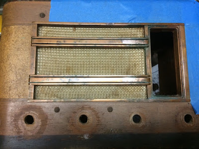
The front grill had a lot of corrosion.  The copper had turned green.


I wasn't sure if it was pure copper or if it was copper over Zinc.  Also not sure if it had a lacquer coating or not.  I decided to try lightly polishing some of the corroded spots with Simichrome polish.


Well, it became pretty clear that this was an "antiqued" copper finish with a lacquer wash over copper.  Polishing was going to turn it all to "bright" copper.  That might not be so bad, but I decided to take a break and move on to electrical work.


One knob was missing from the front.  Fortunately, I keep knobs in stock.  I found one that would work for now.  I'll revisit this later and see if I can get them all to match.


Looking at the electrical, the radio still had an original service tag.  Apparently this radio used to live in Whitehall Montana and was repaired in Butte Montana in 1946.  I can imagine a late 30's or early 40's car taking the 26.6 mile trip from Whitehall to Butte to get the family radio repaired.


I opened up the radio and found it pretty dusty dirty inside. Some compressed air worked out much of the dust.


The tube sleeves were pretty rusty.  I thought it would be nice to clean them up so I made use of my favorite rust remover - Evapo-Rust.


After time in the Evapo Rust, At least the covers are not brown any more.  I suppose if I was really ambitious I could polish them.


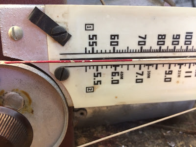
This radio had a bit of an unusual dial.  It's simply the dial cord strung through the dial and painted red.  It needed some touch up so I touched it up with model paint. 


Electrical - Capacitors

Quickly identified a leaky capacitor.


There was also a large paper capacitor.  Considering the swelling, this was probably something I was going to need to replace, but replace with what??


There were no markings except for some numbers that were barely legible.  This one was a bit of a mystery.   Was that 159? 459? Then 63?  Were these values? Part numbers? voltages?


Fortunately, I was able to find a schematic on the Nostalgia Air site!  Love this site!  Thank you SO MUCH to these folks!!!

Looking at the schematic, it listed a capacitor number 459.  Hmmm... that might be a 459. That would make this a three section capacitor with each section being 10mfd.  Since there were 4 wires, this seemed plausible.  Let's go with that!


Rather than cut and remove, I wanted to keep the original appearance.  I decided to open up the
old foil/paper capacitor and solder new capacitors inside.   First I had to remove the original foil and tar.


I then was able to get to the leads inside the paper shell.


\

Here it is with the new capacitors safely installed within the old paper shell. 


I had muddled audio on the output. I expect the the connector capacitor between the 6C5 and the #43 tube which carries the audio from one tube to the other.  I replaced it and that cleaned things up. 


Electrical - Tubes

The schematic listed the following tubes for this radio.
  • 6A7 - Oscillator / Mixer
  • 6D6 - IF Amplifier
  • 6H6 - Dtector / A.V.C.
  • 6C5 - 1'st A.F. 
  • 43 - Audio Output
  • 25Z5 - Rectifier 


Two of the six tubes in this radio still bore the original Kadette brand name which means they likely were originals.  This is not uncommon on the radios I check.  Tubes last a very long time.


This radio actually had a 7th "Tube".  It's a ballast which is more or less a light bulb.  The tubes are all in series so their filament voltage needs to add up to 115V.  Without this tube, they only add up to 74 volts.   This little heater sits there and gobbles up current to keep the voltage in line. 


Unfortunately, one tube was missing.  The number 43.  It's a 25v audio output tube. 


Now, normally, this would not be a problem since I keep a lot of tubes in stock.


Though, I didn't have any number 43 tubes so I had to source one.   I found one on line and got it in place.


The radio lit up but did not play.   Turns out I had two other bad tubes that had to be swapped out.  The 25Z5 was lighting up but not putting out any voltage.  The 6C5 was dead and my tube tester verified that.  Then the anode cap was falling off on the 6D6 IF amplifier. I didn't want to try repairing it.  I just replaced it.


All in all, this meant 3 bad tubes and one missing.  That's more tube replacement than I normally have to do, but this is a rather old radio and looks to have been used quite a bit.


The electrical cord was looking pretty bad so I wanted to swap it out.  I wanted something that looked period correct.  Turns out they had a fabric covered extension cord at Target.  I used that.


The radio is playing fine and sounds clear and strong on the AM broadcast band.  The radio is supposed to cover short wave bands and I'm not getting anything on there so I'll need to revisit it. Work on this radio continues. I'll update the blog post when I pick it back up again.