My dad picked up this radio at a garage sale and passed it on to me as a project. He hadn't done any testing or opened it up so condition was unknown. Here's how it looked when it arrived on my workbench ready for a look.
The International Radio Corporation started making radios in 1931 and became somewhat famous for their Kadette series of radios.
The founders later diversified into the camera business to form the Argus camera company which was a 50's icon of American photography. (
More info here) I have a few of these cameras that all need work. Maybe I'll make those a weekend project some time and create a new blog post. :)
Cosmetic Work
The front grill had a lot of corrosion. The copper had turned green.
I wasn't sure if it was pure copper or if it was copper over Zinc. Also not sure if it had a lacquer coating or not. I decided to try lightly polishing some of the corroded spots with
Simichrome polish.
Well, it became pretty clear that this was an "antiqued" copper finish with a lacquer wash over copper. Polishing was going to turn it all to "bright" copper. That might not be so bad, but I decided to take a break and move on to electrical work.
One knob was missing from the front. Fortunately, I keep knobs in stock. I found one that would work for now. I'll revisit this later and see if I can get them all to match.
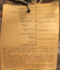
Looking at the electrical, the radio still had an original service tag. Apparently this radio used to live in Whitehall Montana and was repaired in Butte Montana in 1946. I can imagine a late 30's or early 40's car taking the 26.6 mile trip from Whitehall to Butte to get the family radio repaired.
I opened up the radio and found it pretty dusty dirty inside. Some compressed air worked out much of the dust.
The tube sleeves were pretty rusty. I thought it would be nice to clean them up so I made use of my favorite rust remover -
Evapo-Rust.
After time in the Evapo Rust, At least the covers are not brown any more. I suppose if I was really ambitious I could polish them.
This radio had a bit of an unusual dial. It's simply the dial cord strung through the dial and painted red. It needed some touch up so I touched it up with model paint.
Electrical - Capacitors
Quickly identified a leaky capacitor.
There was also a large paper capacitor. Considering the swelling, this was probably something I was going to need to replace, but replace with what??
There were no markings except for some numbers that were barely legible. This one was a bit of a mystery. Was that 159? 459? Then 63? Were these values? Part numbers? voltages?
Fortunately, I was able to find a
schematic on the Nostalgia Air site! Love this site! Thank you SO MUCH to these folks!!!
Looking at the schematic, it listed a capacitor number 459. Hmmm... that might be a 459. That would make this a three section capacitor with each section being 10mfd. Since there were 4 wires, this seemed plausible. Let's go with that!
Rather than cut and remove, I wanted to keep the original appearance. I decided to open up the
old foil/paper capacitor and solder new capacitors inside. First I had to remove the original foil and tar.
I then was able to get to the leads inside the paper shell.
\

Here it is with the new capacitors safely installed within the old paper shell.
I had muddled audio on the output. I expect the the connector capacitor between the 6C5 and the #43 tube which carries the audio from one tube to the other. I replaced it and that cleaned things up.
Electrical - Tubes
The schematic listed the following tubes for this radio.
- 6A7 - Oscillator / Mixer
- 6D6 - IF Amplifier
- 6H6 - Dtector / A.V.C.
- 6C5 - 1'st A.F.
- 43 - Audio Output
- 25Z5 - Rectifier
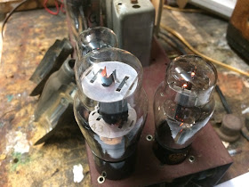
Two of the six tubes in this radio still bore the original Kadette brand name which means they likely were originals. This is not uncommon on the radios I check. Tubes last a very long time.
This radio actually had a 7th "Tube". It's a ballast which is more or less a light bulb. The tubes are all in series so their filament voltage needs to add up to 115V. Without this tube, they only add up to 74 volts. This little heater sits there and gobbles up current to keep the voltage in line.
Unfortunately, one tube was missing. The number 43. It's a 25v audio output tube.
Now, normally, this would not be a problem since I keep a lot of tubes in stock.
Though, I didn't have any number 43 tubes so I had to source one. I found one on line and got it in place.
The radio lit up but did not play. Turns out I had two other bad tubes that had to be swapped out. The 25Z5 was lighting up but not putting out any voltage. The 6C5 was dead and my tube tester verified that. Then the anode cap was falling off on the 6D6 IF amplifier. I didn't want to try repairing it. I just replaced it.
All in all, this meant 3 bad tubes and one missing. That's more tube replacement than I normally have to do, but this is a rather old radio and looks to have been used quite a bit.
The electrical cord was looking pretty bad so I wanted to swap it out. I wanted something that looked period correct. Turns out they had a fabric covered extension cord at Target. I used that.
The radio is playing fine and sounds clear and strong on the AM broadcast band. The radio is supposed to cover short wave bands and I'm not getting anything on there so I'll need to revisit it. Work on this radio continues. I'll update the blog post when I pick it back up again.


